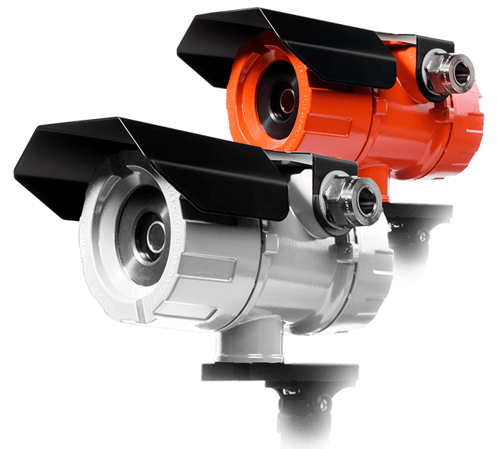
FLAME DETECTORS GROUP «VEGA»
FD 330-1-4: 4 IR channels
FD 330/329-2-4: 3 IR channels + 1 UF channel
Reliable detection of combustion sources in all weather conditions.
Unrivaled noise-immunity.
Features
Functionality
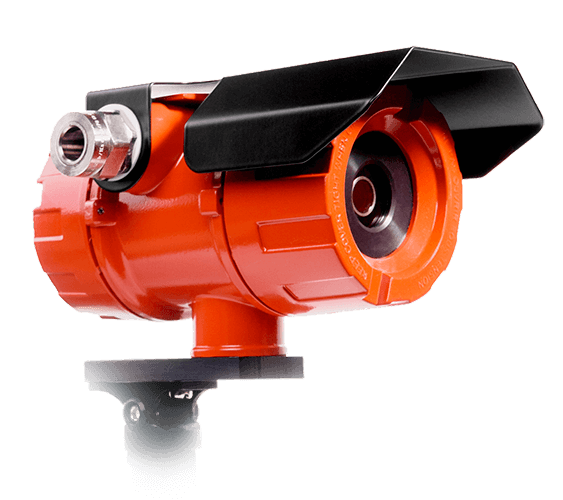
Flame detectors FD 330-1-4 and FD 330/329-2-4 are intended for use in fire alarm systems and to issue an alarm signal to the devices of reception and fire control and fire security in the event of a fire in the controlled area.
Due to high immunity to climatic and mechanical stress as well as to sun outage, detectors can be installed both indoors and outdoors.
Application Scope
Recommended for use in automatic fire alarm systems with fire extinguishing and technological systems with HART, Modbus (RTU) protocols at facilities with tough operating conditions:
- Land and marine oil production and treatment facilities associated with gas flaring; plants that discharge and burn gas, refineries, oil depots, gas processing plants, gas pipelines and oil pipelines, compressor substations;
- Metallurgical foundries and rolling industries, machinery and shipbuilding industries with a large number of welding works;
- Aircraft and helicopter plants, repair hangars and other production facilities at airports;
- Chemical plants;
- Hazardous areas of underground mines and quarries and of surface structures (shafts, drifts, adits, conveyors, skip hoisting plants, etc.)
Flame detector comes in two modifications:
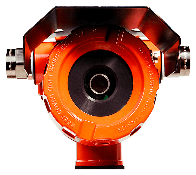
FD 330-1-4 model differences:
- Combustion sources detection by 4 IR channels;
- False sources rejection is made by intelligent algorithm based on the optical and frequency spectral analysis;
- Optics dirt detection is made by an IR optocouple.
Marking when ordering:
FD 330-1-4
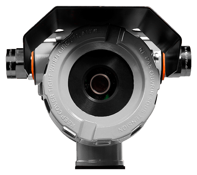
FD 330/329-2-4 model differences:
- Combustion sources detection by 3 IR channels and 1 UV channel;
- UV channel rejects false sources;
- Optics dirt detection is made by an UV optocouple.
Marking when ordering:
FD 330/329-2-4
Contents of delivery
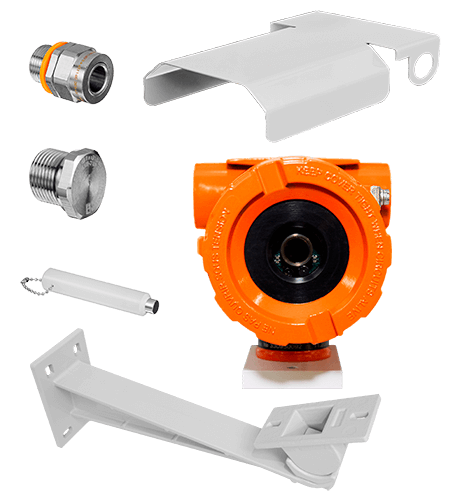
- Detector «Vega»
- EX-proof cable gland
- EX-proof end plug
- Magnetic key
- Sunshield
- Mounting bracket
- Software for calibration and tuning
- Datasheet
SPECIFICS
-60 °C … +85 °C
80-120 kPa
0-100%
(w/o condensation)
160х110х100 mm
< 2 kg
OPERATING PRINCIPLE
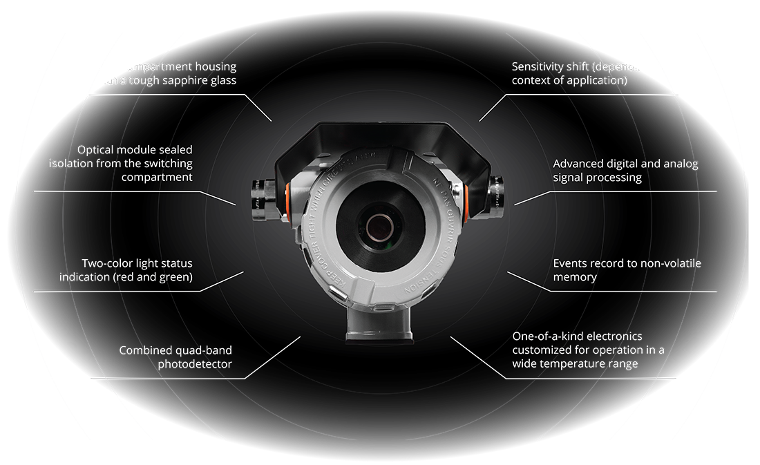
Flame detectors FD 330-1-4 and FD 330/329-2-4 are electro-optical devices analyzing IR (FD 330-1-4) or IR and UV (FD 330/329-2-4) radiation in the controlled area. The photocells of the detectors are selected in such a way as to provide maximum sensitivity at wavelengths typical for combustion products (heated water molecules and carbon dioxide). The presence of combustion sources is determined by identifying signs of optical radiation in various wavelength ranges, characteristic exceptionally for fire.
Determining the combustion algorithm of detectors is also supplemented by optical radiation spectra frequency analysis that gives a greater degree of certainty while determining false radiation sources such as sun glare, turning on/off lamps, the operation of heated equipment, and lightning strokes.
The detectors have a self-testing function that provides automatic control of the operability of the detector electronic circuits. During an automatic functional check, the detector independently detects the photocells viewing window dirt, and also checks the operability of each of the optical channels. Besides, the temperature and parameters of the external power supply of the detector are monitored. In case of failure or optics dirt detection, the detector generates a «FAILURE» signal.


TECHNICAL CHARACTERISTICS |
|
| Sensitiveness class (according to GOST R 53325) | 4 |
| Flame detection range: | |
| – TF-5 (combustion with smoke emission) | 60 m |
| – TF-6 (smokeless combustion) | 50 m |
| – Hydrogen flame (0,8 m) | 30 m |
| – Hydrocarbon gas flame (0,8 m) | 20 m |
| Response time: | |
| – TF-5, 60 m distance | < 10 s |
| – TF-6, 30 m distance | < 10 s |
| – TF-6, 50 m distance | < 20 s |
| – Hydrogen flame (0,8 m), 30 m distance | < 10 s |
| – Hydrocarbon gas flame (0,8 m), 20 m distance | < 10 s |
| Viewing angles: | |
| – in vertical direction | > 90° |
| – In horizontal direction | > 90° |
| Readiness time upon actuation | < 60 s |
POWER SUPPLY PARAMETERS |
|
| Supply voltage | 9-32 VDC |
| Power consumption: | |
| – standby mode | < 2 W |
| – alarm mode | < 3 W |
SECURITY PARAMETERS |
|
| EX-marking | 1 Ex d IIC T5 X |
| Protection | IP 67 |
FAILURE SAFETY PARAMETERS |
|
| MTBF | > 100 000 hours |
| Average lifetime | 10 years |
OUTPUT INTERFACES |
|
| Current loop: | |
| – max load | 500 Ohm |
| – operation mode | active |
| HART: | |
| – HART protocol version | rev.7 (with previous rev support) |
| RS-485: | |
| – max device on single line | up to 256 |
| – max voltage (between A and B lines and between signal lines and interface ground) | ±12 VDC |
| Relays: | |
| – number and functions | 2 («FIRE», «FAILURE») |
| – max supply voltage, DC | 60 V |
| – max current, DC | 2 А |
| – max supply voltage, AC | 230 V |
| – max current, AC | 2 А |
